Finally, I've got a working stepper motor!
- georgie h
- Apr 26, 2021
- 2 min read
After months of being completely bewildered by stepper motors and all the complications that come with working with them, I've finally worked out how to power and wire up my stepper motors.
Set-up:
What I am using:
x6 Male/Female wires
x1 Male/Male wire
x1 soldered USB power connector
x1 Arduino USB

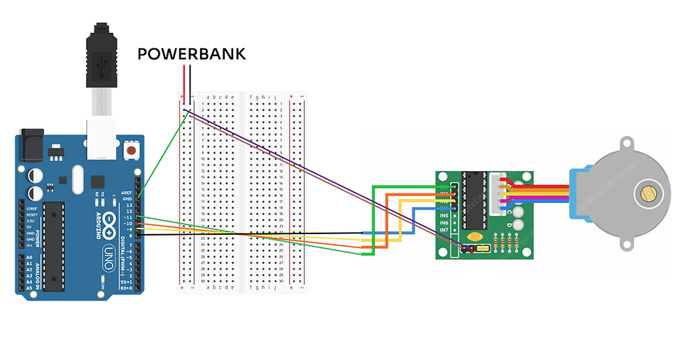
Above a diagram of the wire set up can be seen, thanks to the remote fabrication service, Anna helped me wire everything up.
Connections:
ULN2003 Driver Board to Arduino UNO
IN1 - Pin 11
IN2 - Pin 10
IN3 - Pin 9
IN4 - Pin 8
Power Bank to Breadboard
Ground wire to 1-
Voltage wire to 1+
Breadboard to Arduino UNO
A connecting wire from 2- to GND (above Pin 13)
Breadboard to ULN2003 Driver Board
2+ to +
3- to -
Does it work?
Once those connections are set up, I tested this using the following code from Drone Bot Workshop which can be found here: Stepper Motors with Arduino – Bipolar & Unipolar (dronebotworkshop.com)
/*
  Stepper Motor Demonstration 1
  Stepper-Demo1.ino
  Demonstrates 28BYJ-48 Unipolar Stepper with ULN2003 Driver
  Uses Arduino Stepper Library

  DroneBot Workshop 2018
  https://dronebotworkshop.com
*/

//Include the Arduino Stepper Library
#include <Stepper.h>

// Define Constants

// Number of steps per internal motor revolution
const float STEPS_PER_REV = 32;

//  Amount of Gear Reduction
const float GEAR_RED = 64;

// Number of steps per geared output rotation
const float STEPS_PER_OUT_REV = STEPS_PER_REV * GEAR_RED;

// Define Variables

// Number of Steps Required
int StepsRequired;

// Create Instance of Stepper Class
// Specify Pins used for motor coils
// The pins used are 8,9,10,11
// Connected to ULN2003 Motor Driver In1, In2, In3, In4
// Pins entered in sequence 1-3-2-4 for proper step sequencing

Stepper steppermotor(STEPS_PER_REV, 8, 10, 9, 11);

void setup()
{
// Nothing  (Stepper Library sets pins as outputs)
}

void loop()
{
  // Slow - 4-step CW sequence to observe lights on driver board
  steppermotor.setSpeed(1);
  StepsRequired  =  4;
  steppermotor.step(StepsRequired);
  delay(2000);

   // Rotate CW 1/2 turn slowly
  StepsRequired  =  STEPS_PER_OUT_REV / 2;
  steppermotor.setSpeed(100);
  steppermotor.step(StepsRequired);
  delay(1000);

  // Rotate CCW 1/2 turn quickly
  StepsRequired  =  - STEPS_PER_OUT_REV / 2;
  steppermotor.setSpeed(700);
  steppermotor.step(StepsRequired);
  delay(2000);

}
The outcome of this code can be seen in the video at the top of the post.
Next Steps:
+ Test the code, break down what the code does and how to work out at what each point the steps are at.
+ Work out how to wire up the LED matrix so that they work together.
Comments